


Views: 0 Author: Site Editor Publish Time: 2026-07-26 Origin: Site


Structural reinforcement forms the backbone of any safe construction site. The integrity of temporary works and permanent structures relies entirely on precise load management and the correct choice of a Steel Support system. Selecting the wrong load-bearing framework introduces severe operational risks. These range from catastrophic structural failure and safety compliance violations to project delays and massive material waste.
Contractors and structural engineers need a rigorous evaluation framework to match specific construction scenarios with the correct equipment. You must balance absolute load-bearing capacity with site constraints, environmental factors, and procurement logistics. This guide breaks down the main types of steel supports used in modern construction. You will learn how to evaluate fixed structural beams against adjustable temporary shoring, understand material grades, and implement strict safety protocols to prevent on-site failures.
Load Requirements Dictate Selection: The choice between fixed structural beams and adjustable temporary shoring must be driven by strict engineering calculations regarding dead, live, and environmental loads.
Adjustability vs. Rigidity: Systems like the telescopic steel prop offer high versatility for temporary shoring, while heavy-duty H-beams provide necessary rigidity for permanent structural frameworks.
Standards and Compliance are Non-Negotiable: Selected systems must meet rigorous regional safety and manufacturing standards (e.g., OSHA, EN 1065 for props, AISC for structural steel) to mitigate failure risks.
Calculating required load-bearing capacities is the first step in specifying any support system. Engineers must account for the dead load of the concrete and formwork alongside the live loads introduced by workers, machinery, and material staging. Safety factors are applied to handle unexpected dynamic loads. Environmental forces, including wind shear and seismic activity, dictate the required lateral stability of the chosen framework. A failure to accurately calculate these combined forces leads directly to overloading and potential collapse. On site, this means verifying that the shoring layout matches the stamped engineering drawings before a single yard of concrete is poured. You have to account for the vibration of concrete vibrators, the impact of pump truck hoses, and the shifting weight of personnel moving across the deck.
Physical site constraints heavily influence the viability of different support footprints. Soil stability and the underlying water table determine whether standard base plates are sufficient or if deep foundation piling is required. Uneven terrain often necessitates highly adjustable systems to maintain a level formwork deck. Spatial limitations within urban job sites can restrict the use of heavy craning equipment, forcing contractors to select modular, man-portable shoring components over massive structural steel beams.
Conduct a thorough geotechnical survey to determine soil bearing capacity.
Map out overhead obstructions that might interfere with crane operations.
Evaluate site access routes for flatbed deliveries of heavy structural components.
Determine the necessity of mudsills or crane mats to distribute loads on soft ground.
Support requirements shift drastically between project phases. Temporary works, such as formwork, falsework, and trenching, demand rapid deployment, adjustability, and easy dismantling. Permanent structural integration requires high-yield-strength fixed components designed for decades of static load-bearing. You must categorize your immediate needs to avoid over-engineering a temporary shore or under-specifying a permanent column. Temporary systems need to be stripped and moved quickly to keep the project on schedule, whereas permanent steel is bolted or welded into place and fireproofed for the life of the building.
I-beams, H-beams, and wide-flange sections form the primary load-bearing frameworks for multi-story buildings and heavy infrastructure. These fixed components provide unparalleled rigidity. H-beams feature thicker center webs and wider flanges, making them ideal for vertical columns that must resist massive compressive forces. I-beams offer an excellent strength-to-weight ratio for horizontal spans, effectively resisting bending moments across wide open spaces. When erecting these members, ironworkers rely on precise fabrication and heavy lifting equipment. The connections—whether bolted shear tabs or full-penetration welds—are just as critical as the beams themselves.
High-clearance structures and exceptionally heavy load scenarios require modular shoring towers. Bridge construction and high-rise concrete slab casting rely on these interconnected systems. Shoring towers integrate vertical load-bearing frames with ledger frames and diagonal bracing to create a rigid, self-supporting matrix. Their modularity allows for rapid assembly while distributing massive concrete dead loads across a wider footprint. Crews assemble these towers in lifts, pinning the frames together and installing cross braces to lock the geometry. Screw jacks at the top and bottom allow for fine-tuning the elevation to match the required camber of the concrete slab.
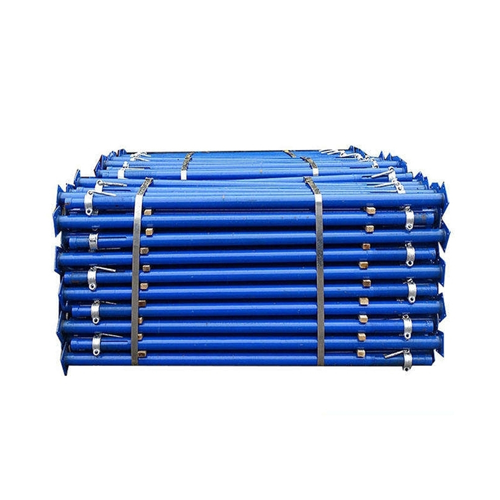
The Telescopic Steel Prop is the standard for temporary slab and beam formwork. These adjustable, threaded tubular supports allow for rapid height modifications on site. They consist of an outer tube, an inner tube, a threaded collar, and a high-strength locking pin. Operational efficiency comes from the ability to quickly dial in the exact height required for a level deck. European standards, such as EN 1065, classify these props (Classes A through E) based on their load capacity at various extension lengths. Capacity decreases as the prop extends, requiring strict adherence to manufacturer load charts. Workers can carry and set these props by hand, making them incredibly efficient for standard floor-to-floor heights in residential and commercial high-rises.
Below-ground excavations require specialized horizontal steel supports. Trench struts and walers hold back retaining walls to ensure worker safety. These systems must withstand immense lateral soil pressure and surcharge loads from adjacent heavy equipment. Trench struts function similarly to vertical props but are engineered specifically for horizontal compression, preventing trench cave-ins during utility installations and foundation work. Hydraulic trench shields and modular aluminum boxes often incorporate steel struts to maintain the required width while allowing excavators to dig safely between the braces.
When surface soils lack the bearing capacity for massive structures, deep foundation elements transfer loads to stable bedrock or dense soil layers. H-piles and steel pipe piles are driven deep into the ground using heavy pile-driving equipment. Interlocking steel sheet piling serves a dual purpose in deep excavations, retaining unstable soil while creating a watertight barrier against groundwater intrusion. Driving sheet piles requires a vibratory hammer suspended from a crane or excavator, and the interlocks must be carefully aligned to ensure a proper seal against water infiltration.
Modern commercial and residential construction frequently utilizes light-gauge cold-formed steel (CFS) studs and tracks. These components act as both load-bearing and non-load-bearing vertical supports. CFS framing offers a lightweight, fire-resistant alternative to traditional timber framing, providing precise dimensional tolerances for interior partitions and exterior curtain walls. Framers cut these studs with abrasive chop saws or metal shears and fasten them using self-tapping screws. The speed of installation and the perfectly straight walls they produce make them a staple in commercial fit-outs.
Fixed structural steel delivers absolute load-bearing capacity and permanent rigidity. However, it requires heavy machinery for placement and offers zero on-site adaptability. Conversely, adjustable systems prioritize rapid deployment and versatility. A temporary shoring prop can be installed by a single worker and adjusted to millimeter precision, though it cannot match the raw compressive strength of a fixed H-beam. You have to weigh the labor cost of erecting heavy steel against the speed and flexibility of modular shoring.
The performance of any steel component is dictated by its metallurgical properties. Common grades like ASTM A36, ASTM A992, or European S235 and S355 denote specific yield strengths. Yield strength represents the maximum stress the steel can handle before permanent deformation occurs. Specifying higher yield strength steel allows engineers to achieve required load limits using lighter, thinner profiles, improving on-site handling and reducing overall material weight.
Steel Grade | Minimum Yield Strength (MPa) | Primary Application |
|---|---|---|
ASTM A36 / S235 | 235 - 250 | General structural plates, standard temporary shoring. |
ASTM A992 / S355 | 345 - 355 | Heavy-duty H-beams, high-stress permanent columns. |
High-Strength Low-Alloy | 450+ | Specialized deep foundation piling, heavy civil engineering. |
Environmental exposure dictates the necessary surface treatment for steel components. Painted and powder-coated finishes offer basic protection for indoor or short-term outdoor use. Electro-galvanized supports resist mild moisture but can degrade under heavy wear. Hot-dip galvanization provides a thick, durable zinc coating that chemically bonds to the steel, offering superior long-term rust prevention for equipment exposed to harsh weather or corrosive coastal environments. If you are working on a marine bulkhead or a bridge over saltwater, bare steel will degrade rapidly, compromising the structural integrity of the entire system.
Vertical steel columns fail through buckling long before the material itself crushes. The slenderness ratio—calculated by dividing the effective length of the column by its radius of gyration (L/r)—dictates this buckling limit. Taller, thinner supports have high slenderness ratios and lower ultimate load capacities. Engineers mitigate buckling in temporary shoring by installing lateral bracing, which effectively reduces the unsupported length of the column. This is why you see diagonal tubes clamped between vertical props on high-clearance concrete pours.
International safety standards govern the manufacturing and deployment of construction supports. Utilizing non-certified equipment introduces massive liability. Site managers must map specific support features to standards like OSHA regulations or EN 1065. Certified load charts provided directly by the manufacturer are the only acceptable reference for determining safe working loads on site. Never guess the capacity of a prop based on its physical size; always verify the stamped rating and cross-reference it with the approved falsework drawings.
Contractors must evaluate whether to purchase support inventory outright or rent equipment for specific durations. Purchasing requires significant upfront capital but provides long-term asset availability for companies with consistent, predictable project pipelines. Renting preserves capital and allows contractors to source specialized shoring systems tailored exactly to a unique project without worrying about long-term storage. If you only pour thick transfer slabs once a year, renting heavy-duty shoring towers makes more sense than buying them and letting them rust in your yard.
Equipment durability heavily impacts the return on investment for contractors who self-perform concrete work. High-quality galvanized shoring props withstand the physical abuse of repeated stripping, stacking, and transport. Proper lifecycle management—including regular thread cleaning and rust prevention—extends the usable life of these assets, maximizing their value across dozens of project cycles. Throwing props off a deck into a pile bends the inner tubes and ruins the threads, turning a valuable asset into scrap metal.
Heavy structural steel demands specialized flatbed transport, massive laydown yards, and high-capacity cranes. This limits logistical flexibility on tight urban sites. Modular, stackable shoring systems reduce transportation volume and can often be moved via standard forklifts or manual labor. You must factor site access and handling capabilities into the initial equipment specification phase. If the crane cannot reach the back corner of the site, you need a shoring system that workers can carry up the stairs.
Applying loads off-center creates dangerous bending moments in vertical supports. Eccentric loading drastically reduces the effective capacity of the column. You must mandate the use of proper head-plates, U-heads, and fork-heads to ensure loads transfer straight down the central axis of the support. Strict structural engineering oversight is required to verify load distribution prior to concrete placement. If a primary beam sits on the edge of a prop head plate rather than dead center, the prop will kick out under load.
Adjustable shoring systems rely entirely on the shear strength of their locking pins. A catastrophic risk arises when workers replace lost manufacturer pins with non-rated components like rebar offcuts or mild steel bolts. These makeshift pins easily shear under heavy concrete loads, leading to immediate progressive collapse. Sites must maintain an inventory of high-strength, manufacturer-approved replacement pins. Supervisors must check every single prop before the concrete pump arrives.
Vertical supports cannot function in isolation under heavy dynamic loads. Failing to install diagonal lacing and horizontal bracing allows lateral movement. This movement increases the slenderness ratio and induces buckling. Temporary shoring towers must be fully braced according to the engineered falsework plan before any load is applied. Missing a single cross brace can compromise the entire tower, especially when the concrete hose surges and shakes the deck.
Worn equipment fails unpredictably. Implement a rigorous protocol for pre-use inspections. Competent personnel must check for thread damage that prevents secure collar locking. Inspect pins for bending or shear wear. Identify physical bends in the inner or outer tubes, corrosion pitting, and micro-fractures near high-stress welded base plates. Quarantine and destroy any compromised components immediately.
Component | Inspection Focus | Failure Consequence |
|---|---|---|
Locking Pins | Check for shear wear, bending, or unauthorized replacements. | Immediate vertical collapse under load. |
Threaded Collars | Ensure smooth rotation and absence of concrete buildup or stripped threads. | Inability to adjust height or hold elevation. |
Inner/Outer Tubes | Look for bowing, dents, or severe corrosion pitting. | Reduced buckling resistance and structural failure. |
Document your exact load requirements, including dead, live, and environmental forces, before selecting any support system.
Consult with a licensed structural engineer to finalize all falsework and permanent framing calculations based on site-specific constraints.
Request detailed technical specifications, product catalogs, and certified load charts from vetted equipment suppliers.
Implement a strict daily inspection protocol to identify and remove damaged shoring components from the active job site.
A: Capacity varies inversely with extended height. Depending on the specific EN 1065 class (A through E) and the extension length, a standard prop typically supports between 10kN and 30kN. Always consult the manufacturer's certified load chart for exact limits at specific heights.
A: The classes define minimum load-bearing capacities at maximum extension. Class E props require a higher minimum load capacity (typically 30kN) compared to Class D (20kN). Class E props feature thicker tube walls and greater overall structural robustness to meet these stringent European standards.
A: Spacing is dictated by the slab thickness, the dead weight of wet concrete, dynamic construction loads, and the specific load chart of the chosen support system. A licensed structural engineer must perform these calculations and approve the final falsework layout plan.
A: H-beams have wider flanges and thicker center webs, providing equal weight distribution that makes them ideal for vertical load-bearing columns. I-beams have narrower flanges and a tapered profile, offering an optimized strength-to-weight ratio for horizontal spans and bending resistance.
A: Renting is preferable for short-term, specialized projects where storage space is limited. Buying is advantageous for contractors with high equipment utilization rates and frequent, similar upcoming projects, provided they have the yard space for long-term storage and maintenance.
A: OSHA mandates that all shoring equipment be inspected by a competent person prior to each shift. Inspections must focus on identifying structural defects, ensuring proper plumbness, verifying secure bracing, and confirming that no damaged components are in use.
A: Hot-dip galvanization provides excellent long-term rust prevention for most outdoor applications. However, in extreme chemical or severe marine environments, standard galvanization may degrade. These situations often require specialized epoxy coatings or alternative corrosion-resistant alloys.


